Antenna rotator finished!
May 4th, 2008 | Last modified: November 8th, 2011
Pictures
This is how it looked like when I got it:


And this is how it looks like now:


More images are here.
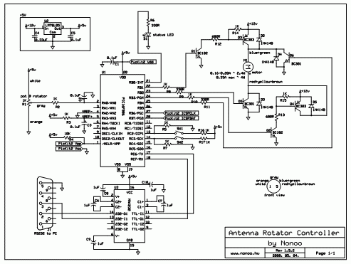
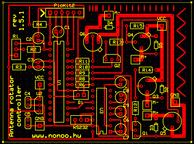
Schematics
The circuit has been designed in PCBExpress, you can download the .sch and .pcb files here.
PDF version of the schematics is here.
Features
- nearly 360° degrees rotation
- error protection – controller stops rotation when the antenna doesn’t turn, but rotation is on, watchdog timer for resetting the controller on failure, bounds checking
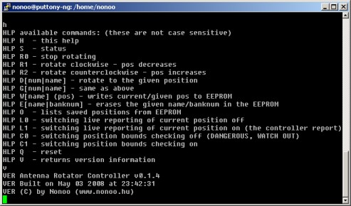
- RS232 (serial port) communication with Hyperterminal (or Minicom on Linux), easy and fast commands, built-in help
- Rotation speed measurement, estimated time calculation ;)
- 16 individual positions can be saved with position names (up to 13 chars), saved in controller EEPROM


About the controller
The controller is a PIC16F886. I used Hi-Tech C compiler for writing the program.
You can download the source code here.
It uses Timer1 for blinking the status LED and Timer2 for pot change protection (there is a pot in the rotator which turns when the rotator is rotating, and if the rotation is on but the pot doesn’t turn, it shuts everything down).
Otherwise the code is (trying to be ;) really simple, so check it out.
There are 4 medium-current transistors, they power the motor with the required voltage polarity. The serial line is handled via a MAX232 IC.
I’ve added 2 buttons in my room near my little desk so I can rotate without using serial console. This is not reflected on the circuit drawing.
Available commands
Previous posts
Rotator demo video #2
Short rotator demo video
Antenna rotator take #2
Antenna rotator renewing
Trackback URL
 Projects


Great invention Nonoo!
I will definitely do it within the next few months, but i was wondering how much did the electronic equipment cost and how much does the motor itself cost?
Thank you.
Huh I don’t remember, it was years ago. Building the circuit cost me around $20-$30 I think. I got the rotator for free from a friend of mine.
Well thanks anyway man, I got all the info I needed.
Great project Nonoo
It is possible to add LCD display to work without PC?
Yes of course :)
can you upload code for controller to use with LCD without using PC with manual CW CCW switch?
Thanks in advance vu2kyz
Hi, my implementation doesn’t use an LCD so I don’t have code for that.
Hello! This is my first visit to your blog! We are
a team of volunteers and starting a new project in a community in the same niche.
Your blog provided us valuable information to work on.
You have done a outstanding job!
hi Nonoo nice project
can you please tell me which program you used for you PCB schematic
ExpressPCB